27+ potentiometer block diagram
Built-in Parameter Calibration Procedure 29 Command Interface 31 Command List 31. Two terminals blue and green are connected to a resistive element and the third.

Adding A Fine And Coarse Potentiometer Electronic Circuit Projects Electronics Basics Electronics Circuit
Potentiometer Antenna 01 Desired azimuth angle input 01 Azimuth angle output Differential amplifier and power amplifier Motor.

. Find the Library pane on the left side of the interface then tap and hold on a block shape. The potentiometer symbol comprises a resistor symbol with an arrow in. Razor mod wiring sport diagram parts electric scooter electricscooterparts version.
The operation principle was adopted from 1 where a low pass filter LPF circuit was installed at the output of the. Potentiometers work by varying the position of a sliding contact across a uniform resistance. The layout schematic and block diagram are shown below.
The ground is generally off terminal 2 is the main switch and the third terminal is the variable switch that can be turned. The block diagram of the digital potentiometer system is shown in Fig. Carefully drag and drop it onto the canvas displayed on the right side of the screen.
Potentiometer is a three-leg device with a sliding or rotating contact used to create variable resistance or voltage. In a potentiometer the entire input voltage is applied across the whole length of the. You can suppose a potentiometer as a dimmer instrument.
Thus this DVM is in fact a self-balancing potentiometerThe potentiometric DVM is provided with a readout which displays the voltage being measured. 27 danjuliodesigns LLC Sparkfun Touch Potentiometer User Manual 1. The Potentiometer Circuit Diagram below shows that a potentiometer has three pins.
Switch throttle wiring diagram potentiometer valve position quattroworld g69 idle schematically. Potentiometer Antenna 01 Desired azimuth angle input 01 Azimuth angle output Differential amplifier and power amplifier Motor. The layout schematic and block diagram are shown below.

Digital Potentiometer Mcp41100 And Arduino Arduino Electronic Engineering Intel Edison

Pin On Electronic S

Dc Dc Mini 5v Step Up Power Boost Converter Module Mini Power Circuit Diagram

Ky 026 Flame Sensor Module Circuit Diagram Circuit Diagram Sensor Diagram

Digital Potentiometer Mcp41100 And Arduino Arduino Led Controller Digital

Potentiometer Circuit Electronics Basics Circuit Diagram Circuit

Arduino Based 4dof Robotic Arm Control In 2022 Arduino Robot Arm Circuit Diagram
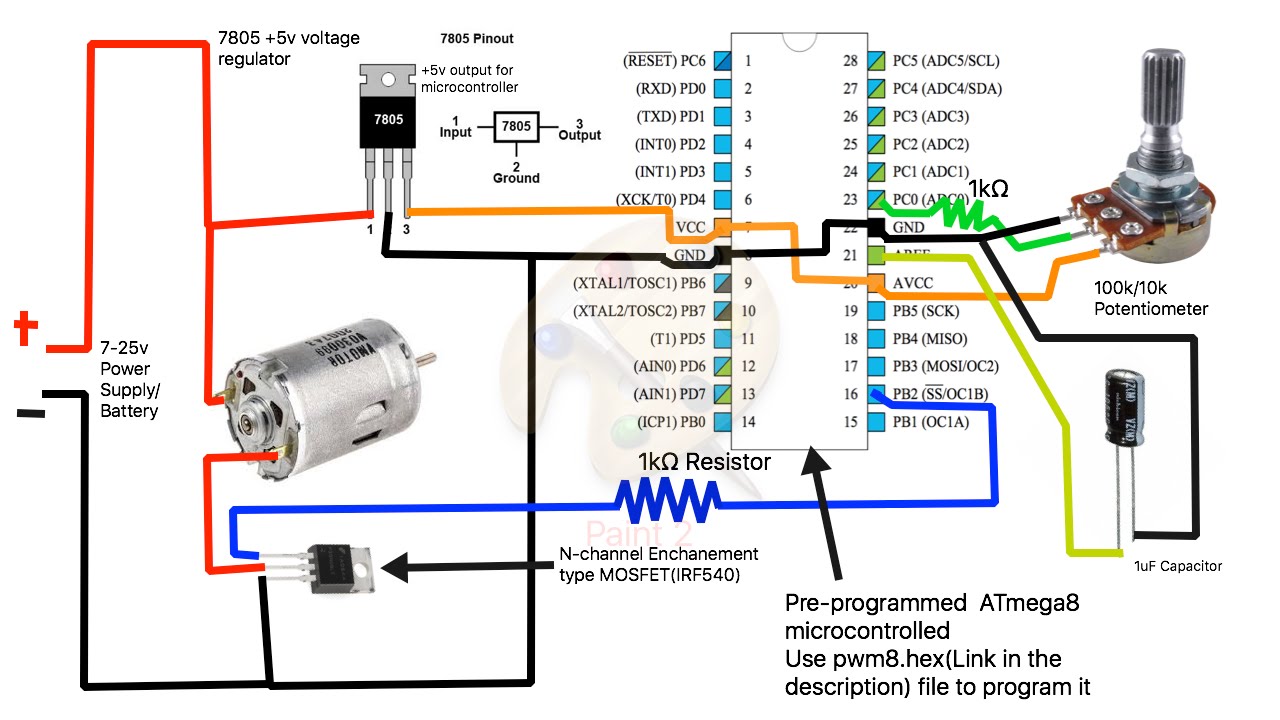
How To Build A Simple Pwm Dc Motor Speed Controller Using Atmega8 Microcontroller Mosfet And Pot Youtube Motor Speed Electronic Schematics Microcontrollers

Potentiometer Is A Three Terminal Resistor With A Sliding Or Rotating Contact That Forms An Adjustable Volt Electronic Engineering Voltage Divider Resistor

Resistors And Potentiometers A Practical Guide Audio Design Electrical Projects Resistors

Vs1103b Midi Synthesizer Electronics Projects Diy Electronics Projects Car Audio Systems

Connecting A Volume Control Potentiometer Pot To An Amp Board Stereo Speaker Box Design Bluetooth Speakers Diy

Update 3 How To Build The Simplest Dc Motor Speed Controller Using Mosfet And Potentiometer Youtube Motor Speed Circuit Diagram Diy Electronics

12v Dc Fan Motor Speed Controller Circuit Diagram Dc Fan Speed Control Circuit Motor Speed Circuit Circuit Diagram
Learn On Off Light And Temperature Controller Using 741 Op Amp Simple Electronic Circuits Temperature Control Control

1 2 36v 5a Adjustable Power Supply With Lm317 Power Supply Circuit Electronic Schematics Electronic Engineering

Digital Volume Control Circuit Esquemas Eletronicos Eletronica Componentes Eletronicos